Tian-Daye on the Way


  • 首页

  • 关于

  • 标签

  • 分类

  • 归档

Qemu-kvm memory 虚拟化

发表于 2019-08-23 | 分类于 Software |

内存虚拟化

内存初始化

qemu的虚拟地址作为guest的物理地地址,guest运行在虚拟的地址空间,但终究是存在物理内存上的,所以要建立虚拟地址空间与物理地址之间的映射。另外,必须要为虚拟机运行程序提供安全的、隔离的运行环境,避免虚拟机之间、虚拟机与宿主机之间的相互干扰。qemu会提前为guest申请好虚拟地址,只有真正需要的时候,通过产生页中断申请物理地址,并且建立页表产生对应关系。

guest对内存的要求

对操作系统从加载到执行的情况来分析,它需要使用一个从0开始的、连续的物理地址空间.在有虚拟机运行的硬件平台上,唯一的物理内存是用于加载、运行宿主机的操作系统的,因此Guest OS是不能直接在物理内存上加载、运行的,唯一可行的办法是为Guest OS 提供一个虚拟的物理内存空间,我们称之为虚拟机物理地址空间,这个虚拟的内存空间是从0开始的、连续的内存空间,也是Guest OS能够感知和管理的虚拟物理内存单元,Guest OS在这个虚拟机物理内存空间的基础上为应用程序分配内存空间,创建页表等;
关键名词:
gva : Guest Virtual Address 虚拟机线性地址
gpa : Guest Physical Address 虚拟机物理地址
gfn : Guest Page Frame Number 虚拟机物理地址空间中一个物理页对应的页帧号
hva : Host Virtual Address 宿主机线性地址
hpa : Host Physical Address 宿主机物理地址
hfn : Host Page Frame Number 宿主机物理地址空间中一个物理页对应的页帧号
pte : Page Table Entry 页表项(包含页表的起始地址及相应访问权限位)
gpte : Guest Page Table Entry 虚拟机页表项
spte : Shadow Page Table Entry EPT表中的页表项

Linux 内核中采用四级页表:
页全局目录 (Page Global Directory, pgd);
页上级目录 (Page Upper Directory, pud);
页中间目录 (Page Middle Directory, pmd);
页表 (Page Table, pt)。

Qemu的内存布局

  1. 关键数据结构罗列
    AddressSpace、 MemoryRegion、 RAMBlock、 FlatView、 MemoryRegionSection、 KVMSlot、AddressSpaceDispatch、 kvm_userspace_memory_region。

  2. 全局内存数据结构
    AddressSpace:address_space_memory、address_space_io;
    MemoryRegion:system_memory、 system_io;

  3. 从数据结构间的关系分析Qemu的内存布局
    qemu中用AddressSpace用来表示CPU/设备看到的内存,两个全局 Address_sapce: address_space_memory、 address_space_io,地址空间之间通过链表连接起来;在一个全局地址空间下挂着一个全局的memoryRegion:system_memory、 system_io。在Qemu中通过一棵memoryRegion树的形式管理着不同的内存区间。MemoryRegion又可分为container, alias, subregions,这些类型用来组织管理整个内存空间。另外,涉及到内存的不同用途,mr又可分为ram, rom, mmio等。 AddressSpace构建了虚拟机的一部分地址空间,而挂载在AddressSpace下的根mr及其子树瓜分了该地址空间。利用 Mr树形结构,将地址空间划分不同的内存域进行分域管理。
  4. 从代码流程分析qemu内存布局
    4.1 地址空间初始化
    两个全局AS:address_space_memory, address_space_io;
    两个全局MR:system_memory、 system_io

    4.11 为AS注册回调函数

    kvm_memory_listener_register(s, &s->memory_listener,&address_space_memory, 0);
    memory_listener_register(&kvm_io_listener,&address_space_io);
    

    4.12 初始化地址空间

    1
    main -> cpu_exec_init_all -> memory_map_init->memory_region_init / address_space_init
    为全局 system\_memory、 system\_io MR分配内存,分别建立全局MR和全局AS的连接。初始化MR和AS的相关成员变量,并且为AS添加与MR相关事件(add, commit)的侦听函数,最后把不同的AS分别加入到全局的address\_spaces链表中,最后调用 memory\_region\_transaction\_commit() 提交本次修改.
    

    4.13 申请内存

    以申请system_memory为例,描述内存申请与管理的流程。 
    
    memory_region_allocate_system_memory - memory_region_init_alias - memory_region_add_subregion
        |
    allocate_system_memory_nonnuma
        |
    memory_region_init_ram
        |
    qemu_ram_alloc
        |
    ram_block_add
        |
    phys_mem_alloc //static void *(*phys_mem_alloc)(size_t size, uint64_t *align) = qemu_anon_ram_alloc;
        |
    qemu_anon_ram_alloc // include/qemu/osdep.h
    qemu_ram_mmap
    mmap       
    

    说明:memory_region_allocate_\system_memory 为一个mr申请了RAM;

     memory\_region\_init\_alias: 将上述mr RAM 分成了低4G的内存和高4G内存的alias.
     memory\_region\_add\_subregion:将alias挂载到system memory下面。
    
    void pc_memory_init(PCMachineState *pcms,
                        MemoryRegion *system_memory,
                        MemoryRegion *rom_memory,
                        MemoryRegion **ram_memory)
    {
        memory_region_allocate_system_memory(ram, NULL, "pc.ram",
                                             machine->ram_size);//为mr分配存储空间
        *ram_memory = ram;
        ram_below_4g = g_malloc(sizeof(*ram_below_4g));
        memory_region_init_alias(ram_below_4g, NULL, "ram-below-4g", ram,0, pcms->below_4g_mem_size);//将 mr ram从0开始偏移的4G设置成"ram-below-4g" alias也是一个mr,但是其ram block为NULL
        memory_region_add_subregion(system_memory, 0, ram_below_4g);//将ram_below_4G挂在system memory下
    
        if (pcms->above_4g_mem_size > 0) {
            ram_above_4g = g_malloc(sizeof(*ram_above_4g));
            memory_region_init_alias(ram_above_4g, NULL, "ram-above-4g", ram,
                                     pcms->below_4g_mem_size,
                                     pcms->above_4g_mem_size);
            memory_region_add_subregion(system_memory, 0x100000000ULL,
                                        ram_above_4g);
        }
    }
    

    分配后的内存模型如下:
    qemu内存布局
    当在qemu中的内存布局发生变化后,需要将这个变化同步到kvm中,这个过程实在上述函数 memory_region_add_subregion 中实现的。

    memory_region_add_subregion -> memory_region_add_subregion_common -> memory_region_update_container_subregions
    -> memory_region_transaction_commit 
    

    memory_region_add_subregion_common 将subrigion的container设置为system_memory,置其addr字段为offset,即在全局MR中的偏移。然后就按照优先级顺序把subregion插入到system_memory的subregions链表中。之后调用函数 memory_region_transaction_commit 进行内存拓扑的同步。

    memory_region_transaction_commit -> address_space_update_topology -> address_space_update_topology_pass 
    

    对于每个address_space,调用address_space_update_topology()执行更新。里面涉及两个重要的函数generate_memory_topology和address_space_update_topology_pass。前者对于一个给定的MR,生成其对应的FlatView,而后者则根据oldview和newview对当前视图进行更新。

    struct FlatView {
        struct rcu_head rcu;
        unsigned ref;
        FlatRange *ranges;//flatrange 数组
        unsigned nr;//flat range 数目
        unsigned nr_allocated;
    };
    /* Range of memory in the global map.  Addresses are absolute. */
    struct FlatRange {
        MemoryRegion *mr;
        hwaddr offset_in_region;//全局mr中的offset,GPA
        AddrRange addr;//地址区间,HVA
        uint8_t dirty_log_mask;
        bool romd_mode;
        bool readonly;
    };
    
    FlatView *old_view = address_space_get_flatview(as)//从as的current_map中获取
    FlatView *new_view = generate_memory_topology(as->root);
    

    如何生成一个新的FlatView:

    generate_memory_topology -> render_memory_region+flatview_simplify
    

    在获取了新旧两个FlatView之后,调用了两次address_space_update_topology_pass()函数,首次调用主要在于删除原来的视图,而后者主要在于添加新的视图。之后设置as->current_map = new_view。并对old_view减少引用,当引用计数为1时会被删除。

    address_space_update_topology_pass
            |
    MEMORY_LISTENER_UPDATE_REGION//将flatrange转化为 MemoryRegionSection
            |
    region_add(kvm_region_add) / region_del(kvm_region_del)
            |
    kvm_set_phys_mem// 将 MemoryRegionSection 记录到 KVMSlot中
            |
    kvm_userspace_memory_region//将 slot中的数据记录到 kvm_userspace_memory_region中,然后调用 KVM_SET_USER_MEMORY_REGION 进入kvm中,kvm_userspace_memory_region 这个结构qemu和kvm共同拥有
    

    MemoryRegionSection -> KVMSlot

    /**
 * MemoryRegionSection: describes a fragment of a #MemoryRegion
 *
 * @mr: the region, or %NULL if empty
 * @address_space: the address space the region is mapped in
 * @offset_within_region: the beginning of the section, relative to @mr's start
 * @size: the size of the section; will not exceed @mr's boundaries
 * @offset_within_address_space: the address of the first byte of the section
 *     relative to the region's address space
 * @readonly: writes to this section are ignored
 */
struct MemoryRegionSection {
    MemoryRegion *mr;
    AddressSpace *address_space;
    hwaddr offset_within_region;
    Int128 size;
    hwaddr offset_within_address_space;
    bool readonly;
};
typedef struct KVMSlot
{
    hwaddr start_addr;//gpa
    ram_addr_t memory_size;
    void *ram;//hva
    int slot;
    int flags;
} KVMSlot;

MemoryRegionSection -> KVMslot?

根据 region 的起始 HVA(memory_region_get_ram_ptr) + region section 在 region 中的偏移量 (offset_within_region) + 页对齐修正 (delta) 得到 section 真正的起始 HVA,填入 userspace_addr
在 memory_region_get_ram_ptr 中,如果当前 region 是另一个 region 的 alias,则会向上追溯,一直追溯到非 alias region(实体 region) 为止。将追溯过程中的 alias_offset 加起来,可以得到当前 region 在实体 region 中的偏移量。
由于实体 region 具有对应的 RAMBlock,所以调用 qemu_map_ram_ptr ,将实体 region 对应的 RAMBlock 的 host 和总 offset 加起来,得到当前 region 的起始 HVA。
根据 region section 在 AddressSpace 内的偏移量 (offset_within_address_space) + 页对齐修正 (delta) 得到 section 真正的 GPA,填入 start_addr
根据 region section 的大小 (size) - 页对齐修正 (delta) 得到 section 真正的大小,填入 memory_size

KVMSlot -> kvm_userspace_memory_region?

    mem.slot = slot->slot | (kml->as_id << 16);
    mem.guest_phys_addr = slot->start_addr;
    mem.userspace_addr = (unsigned long)slot->ram;
    mem.flags = slot->flags;

/* for KVM_SET_USER_MEMORY_REGION */
struct kvm_userspace_memory_region {
    __u32 slot;//slot编号
    __u32 flags;//标志位,是否需要追踪对该页的写、是否可读等
    __u64 guest_phys_addr;//gpa
    __u64 memory_size; /* bytes,内存大小 */
    __u64 userspace_addr; /* start of the userspace allocated memory ,HVA*/
}//

在qemu中的整个拓扑图如下,至此,内存管理在Qemu中的流程结束。
qemu内存模型传递图

在Qemu中调用kvm提供的kvm_userspace_memory_region API进行访问,函数链如下:

kvm_vm_ioctl_set_memory_region() -> kvm_set_memory_region(kvm, mem) -> __kvm_set_memory_region(kvm, mem)

两个关键数据结构:

    struct kvm_userspace_memory_region {
    __u32 slot;//slot编号
    __u32 flags;//标志位,是否需要追踪对该页的写、是否可读等
    __u64 guest_phys_addr;//gpa
    __u64 memory_size; /* bytes,内存大小 */
    __u64 userspace_addr; /* start of the userspace allocated memory ,HVA*/
}//
    struct kvm_memory_slot {
    gfn_t base_gfn;// slot的起始gfn
    unsigned long npages;//page数量
    unsigned long *dirty_bitmap;//脏页记录表
    struct kvm_arch_memory_slot arch;//结构相关,包括 rmap 和 lpage_info 等
    unsigned long userspace_addr;//对应的起始 HVA
    u32 flags;
    short id;
};

__kvm_set_memory_region: kvm_userspace_memory_region -> kvm_memory_slot

常规检查,内存大小是否小于一页等。
调用id_to_memslot来获得kvm->memslots中对应的memslot指针;
设置memslot的base_gfn、npages等域;
处理和已经存在的memslots的重叠;
调用install_new_memslots装载新的memslot;
将会根据新的npages变量和原来的npages变量来判断用户的操作属于哪一类:
    KVM_MR_CREATE:现在有页而原来没有,则为新增内存区域,创建并初始化 slot;
    KVM_MR_DELETE: 现在没有页而原来有,则为删除内存区域,将 slot 标记为 KVM_MEMSLOT_INVALID;
    KVM_MR_FLAGS_ONLY / KVM_MR_MOVE:现在有页且原来也有,则为修改内存区域,如果只有 flag 变了,则为     KVM_MR_FLAGS_ONLY ,目前只有可能是 KVM_MEM_LOG_DIRTY_PAGES ,则根据 flag 选择是要创建还是释放     dirty_bitmap;如果 GPA 有变,则为 KVM_MR_MOVE ,需要进行移动。其实就直接将原来的 slot 标记为     KVM_MEMSLOT_INVALID,然后添加新的.

至此,从qemu到kvm的整个内存管理体系建立起来了,从qemu中将AS以flatview的形式展示出来,然后翻译成为slot,然后以kvm_userspace_memory_region 为中介传递至kvm,该结构记录了GPA->HVA,最后在kvm中以kvm_memory_slot的形式保存下来。但是在申请内存之后并没有建立与物理页的连接,该部分的连接工作将由kvm来处理。guest在访问内存的时候,首先通过guest内部的mmu建立页表转换机制,当发现物理页不可访问的时候发生EPT Violation。

EPT Violation

当 Guest 第一次访问某个页面时,由于没有 GVA 到 GPA 的映射,触发 Guest OS 的 page fault,于是 Guest OS 会建立对应的 pte 并修复好各级页表,最后访问对应的 GPA。由于没有建立 GPA 到 HVA 的映射,于是触发 EPT Violation,VMEXIT 到 KVM。 KVM 在 vmx_handle_exit 中执行 kvm_vmx_exit_handlers[exit_reason],发现 exit_reason 是 EXIT_REASON_EPT_VIOLATION ,因此调用 handle_ept_violation 。
首先看一下调用的函数链,从整体感受一下。

handle_ept_violation -> kvm_mmu_page_fault(gpa) -> vcpu->arch.mmu.page_fault(tdp_page_fault) ;

函数handle_ept_violation中,vmcs_readl(EXIT_QUALIFICATION)获取 EPT 退出的原因,EXIT_QUALIFICATION 是 Exit reason 的补充;vmcs_read64(GUEST_PHYSICAL_ADDRESS)获取发生缺页的 GPA;根据 exit_qualification 内容得到 error_code,可能是 read fault / write fault / fetch fault / ept page table is not present;

tdp_page_fault 函数是主要的处理过程:

static int tdp_page_fault(struct kvm_vcpu *vcpu, gva_t gpa, u32 error_code,
          bool prefault)
{
    gfn_t gfn = gpa >> PAGE_SHIFT;//得到子机的gfn
    force_pt_level = !check_hugepage_cache_consistency(vcpu, gfn,
                               PT_DIRECTORY_LEVEL);
    level = mapping_level(vcpu, gfn, &force_pt_level);//计算gfn在页表中所属level,4kB下通常为1,大页通常为2,物理页为大页时,3级页表
    if (fast_page_fault(vcpu, gpa, level, error_code))///尝试快速修复page fault,让CPU重新尝试发生page fault的操作
        return RET_PF_RETRY;

    mmu_seq = vcpu->kvm->mmu_notifier_seq;
    smp_rmb();

    if (try_async_pf(vcpu, prefault, gfn, gpa, &pfn, write, &map_writable))
        return RET_PF_RETRY;

    r = __direct_map(vcpu, write, map_writable, level, gfn, pfn, prefault);

    return r;
}

tdp_page_fault()
-> mapping_level //计算页表级别,4kB下通常为1,大页通常为2,物理页为大页时,3级页表
-> fast_page_fault()//尝试快速修复page fault,让CPU重新尝试发生page fault的操作,热迁移时的write protection导致子机的write page fault,快速修复
以下情况下可执行fast page fault:

       - many spurious page fault due to tlb lazily flushed
       - lots of write-protect page fault (dirty bit track for guest pte, shadow
        page table write-protected, frame-buffer under Xwindow, migration, ...)
-> try\_async\_pf() //将gfn转化为pfn,直接请求或者异步请求,关于异步pf,可以选择是否支持,可以通过配置来决定。

-> try_async_pf()-> kvm_vcpu_gfn_to_memslot => __gfn_to_memslot//找到gfn对应的slot
                 -> __gfn_to_pfn_memslot//寻找gfn对应的pfn,不允许io wait
                     -> __gfn_to_hva_many -> __gfn_to_hva_memslot//计算gfn对应的起始 HVA,slot->userspace_addr + (gfn - slot->base_gfn) * PAGE_SIZE;
                    -> hva_to_pfn //计算 HVA 对应的 pfn,同时确保该物理页在内存中
                        -> hva_to_pfn_fast//
                        -> hva_to_pfn_slow//申请物理页,即为pfn赋值,可能会sleep,可能会等待swap page载入
                -> kvm_arch_setup_async_pf//支持异步
                -> __gfn_to_pfn_memslot//允许io wait

-> __direct_map // 更新 EPT,将新的映射关系逐层添加到 EPT 中

    -> for_each_shadow_entry//根据传进来的gpa进行计算,level-4页表开始,一级一级地填写相应页表项
        -> mmu_set_spte//到达level层后设置页表项
        -> is_shadow_present_pte//中间某一层页表页没有初始化时执行下列函数
            -> kvm_mmu_get_page//新建一个页表页
            -> link_shadow_page //将新建的页表页连接到上一层页表的spetp上
                -> mmu_spte_set(sptep, spte);//为当前页表项的值 (*spetp) 设置下一级页表页的 HPA
                mmu_page_add_parent_pte(vcpu, sp, sptep)-> pte_list_add//将当前项的地址 (spetp) 加入到下一级页表页的 parent_ptes 中,做反向映射

反向映射:每一级页表的spetp指向下一级页表的HPA,同时下一级页表页的parent_ptes反向指向该级别的页表项。这样,当Host需要将guest的某个GPA对应的page移除时,可直接通过反向索引找到该gfn的相关表项进行修改;

关键函数 try_async_pf 的详细解释:
在该函数中首先会尝试寻找gfn对应的pfn,如果找到就返回;

slot = kvm_vcpu_gfn_to_memslot(vcpu, gfn);
async = false;
//已经找到pfn,不需要异步,返回,执行过程中,如果需要IO wait,则不等待
*pfn = __gfn_to_pfn_memslot(slot, gfn, false, &async, write, writable);`
if (!async)
    return false; /* *pfn has correct page already */`

//判断是否能够调用异步机制,如果可以就使用异步机制
if (!prefault && kvm_can_do_async_pf(vcpu)) {//判断vcpu是否允许注入中断
    trace_kvm_try_async_get_page(gva, gfn);
    if (kvm_find_async_pf_gfn(vcpu, gfn)) {//是否已经为该gfn建立了异步寻页机制呢?
        trace_kvm_async_pf_doublefault(gva, gfn);
        kvm_make_request(KVM_REQ_APF_HALT, vcpu);//暂停vcp,等待 异步过程完成后在进入guest
        return true;
    } else if (kvm_arch_setup_async_pf(vcpu, gva, gfn))//建立异步寻页机制,向guest注入中断
        return true;
}

//不能使用异步机制就等待为gfn分配pfn,此时允许 IO wait
*pfn = __gfn_to_pfn_memslot(slot, gfn, false, NULL, write, writable);
return false;

建立异步寻页机制:

kvm_arch_setup_async_pf 、kvm_async_page_present_sync 函数中分别会将 KVM_PV_REASON_PAGE_NOT_PRESENT 和 KVM_PV_REASON_PAGE_READY 中断以 KVM_REQ_EVENT形式注入到子机,子机中会调用 do_async_page_fault 函数处理中断。总的来说,对于swapout mem,可以选择异步模式获取物理页。向guest中发送async page fault 中断,可以帮助子机切换进程,物理页取回来之后再告诉子机把原来的进程调度回来。当子机不能切换进程,此时可以暂停子机。大致流程见下图:
异步寻页机制

Qemu-kvm CPU虚拟化

发表于 2019-08-23 | 分类于 Software |

Qemu-kvm cpu虚拟化简要分析

CPU 虚拟化综述

概要

本文讲述的cpu虚拟化流程基于硬件辅助的虚拟化技术,硬件辅助的虚拟化技术包括Intel virtualization Technology(Intel VT) 和 AMD的 AMD virtualization(AMD V),本文以Intel VT技术为主。关于CPU虚拟化,Intel在CPU硬件层面提供了虚拟化支持 VT-x。之所以使用硬件辅助的主要原因在于纯软件实现全虚拟化的低效性和虚拟化漏洞。

VT-x技术简介

通常,CPU支持ring0~ring3 4个等级,但是Linux只使用了其中的两个ring0,ring3。当CPU寄存器标示了当前CPU处于ring0级别的时候,表示此时CPU正在运行的是内核的代码。而当CPU处于ring3级别的时候,表示此时CPU正在运行的是用户级别的代码。当发生系统调用或者进程切换的时候,CPU会从ring3级别转到ring0级别。ring3级别是不允许执行硬件操作的,所有硬件操作都需要内核提供的系统调用来完成.
为了从CPU层面支持VT技术,Intel在 ring0~ring3 的基础上, 扩展了传统的x86处理器架构,引入了VMX模式,VMX分为root和non-root。VMM运行在VMX root模式;Guest运行在VMX non-root模式。下图给出了Intel VT-x技术的概要。
Intel VT-x
在VT-x技术中引入VMCS (Virtual-Machine Control Structure) 结构,在这个结构中分别保存了客户机的执行环境和宿主机的执行环境,在发生VM-Exit时,硬件自动保存当前的上下文环境到VMCS的客户机状态域中,同时从VMCS的宿主机状态域中加载信息到CPU中;在发生VM-Entry时,CPU自动从VMCS的客户机状态域中加载信息CPU中;这样就实现了由硬件完成上下文的切换。

VMCS

Vmcs是vmx操作模式下的一个重要结构,这里简要说一下。VMCS保存虚拟机的相关CPU状态,每个VCPU都有一个VMCS,每个物理CPU都有VMCS对应的寄存器(物理的),当CPU发生VM-Entry时,CPU则从VCPU指定的内存中读取VMCS加载到物理CPU上执行,当发生VM-Exit时,CPU则将当前的CPU状态保存到VCPU指定的内存中,即VMCS,以备下次VMRESUME。

VMLAUCH指VM的第一次VM-Entry,VMRESUME则是VMLAUCH之后后续的VM-Entry。VMCS下有一些控制域:
VMCS 控制域

vCPU的创建与初始化

在qemu中提供了一个线程供一个vcpu的创建与运行。

简述

vCPU本质是一个结构体,该结构体包括 id, 虚拟寄存器组,状态信息等等。在用户层面维护一个CPU结构体,包括vcpu fd, kvm_run等,通过ioctl前往kvm中访问。在 kvm层面,申请vCPU的结构体,保存相关的运行状态变量等等。

Qemu 层面

函数调用链:

pc_init1 -> pc_cpus_init(pcms) -> pc_new_cpu -> cpu_x86_create -> X86_CPU -> object_new -> ... -> x86_cpu_realizefn

cpu_x86_creat: 生成一个x86结构的CPU结构体,存在qemu层面,记录vcpu的fd, kvm_run状态等。

x86_cpu_realizefn -> qemu_init_vcpu(cs) -> qemu_kvm_start_vcpu

qemu_init_vcpu:初始化cpu相关属性

cpu->nr_cores = smp_cores;
cpu->nr_threads = smp_threads;
cpu->stopped = true;
...
if (kvm_enabled()) {
    qemu_kvm_start_vcpu(cpu);

qemu_kvm_start_vcpu:为cpu生成一个线程,利用该线程创建vcpu,确保vcpu创建成功

cpu->thread = g_malloc0(sizeof(QemuThread));
qemu_thread_create(cpu->thread,thread_name,qemu_kvm_cpu_thread_fn,cpu, QEMU_THREAD_JOINABLE);
while (!cpu->created) {
    qemu_cond_wait(&qemu_cpu_cond, &qemu_global_mutex);//等待cpu创建成功,关于锁还需要了解
}

在vcpu线程中调用KVM提供的 KVM_CREATE_VCPU API到KVM中申请vcpu的创建。创建成功后,建立kvm_run的映射,这样在qemu层中也可以读出kvm中vcpu的运行状态。当然,也会调用其他API从qemu中设置vcpu,例如 cpu id, TSC等等。

qemu_kvm_cpu_thread_fn -> kvm_init_vcpu -> kvm_ioctl
                                        -> kvm_arch_init_vcpu

qemu_kvm_cpu_thread_fn:

cpu->can_do_io = 1;
current_cpu = cpu;

r = kvm_init_vcpu(cpu);

cpu->kvm_run = mmap(NULL, mmap_size, PROT_READ | PROT_WRITE, MAP_SHARED,
            cpu->kvm_fd, 0);//qemu和kvm建立映射,便于信息同步

/* signal CPU creation */
cpu->created = true;//标识cpu创建成功
qemu_cond_signal(&qemu_cpu_cond);//唤醒主线程

至此CPU的初始化流程在Qemu层面基本结束.这样,在qemu层面维护了一个CPU结构体,该结构体的kvm_run成员通过内存映射和KVM中的VCPU进行信息共享;通过kvm中提供的文件描述符和相关API,在qemu层面对kvm中的vcpu进行设置,达到用户对子机CPU进行配置的目标。

Kvm 层面,创建vcpu的过程

函数调用链

kvm_vm_ioctl_create_vcpu -> kvm_arch_vcpu_create-> vmx_create_vcpu -> kmem_cache_zalloc
                                                -> vmx_vcpu_setup
                         -> kvm_arch_vcpu_setup -> vcpu_load
                         -> create_vcpu_fd 

关键函数简要分析:
VPCU创建的整体流程:

static int kvm_vm_ioctl_create_vcpu(struct kvm *kvm, u32 id)
{
    vcpu = kvm_arch_vcpu_create(kvm, id);
    r = kvm_arch_vcpu_setup(vcpu);
    kvm_get_kvm(kvm);//引用计数+1,kvm_put_kvm 引用计数减1,为0时销毁kvm
    r = create_vcpu_fd(vcpu);//生成一个fd,返回到userspace中
}

kvm_arch_vcpu_create 与架构相关的申请与初始化工作,例如创建vcpu的mmu

//x86.c
struct kvm_vcpu *kvm_arch_vcpu_create(struct kvm *kvm,
                    unsigned int id)
{
        vcpu = kvm_x86_ops->vcpu_create(kvm, id);//实际调用 vmx_create_vcpu
        ...
        vmx_vcpu_setup(vmx);// 调用vmx_vcpu_setup来设置VCPU进入非根模式下寄存器的相关信息,这个函数主要是设置VMCS数据结构中客户机状态域和宿主机状态域信息,以确保在进行VM-Entry 时,VCPU可以在非根模式下正确运行,发生VM-Exit时,也可正确切换回KVM执行环境;
        vmx_vcpu_put(&vmx->vcpu);
        put_cpu();//允许抢占->执行调度->任务切换

}

// vmx.c
static struct kvm_vcpu *vmx_create_vcpu(struct kvm *kvm, unsigned int id)
{
    vmx = kmem_cache_zalloc(kvm_vcpu_cache, GFP_KERNEL_ACCOUNT);//为kvm_vcpu申请内核内存
    vmx->vpid = allocate_vpid();//分配标识符
    vmx->guest_msrs = kmalloc(PAGE_SIZE, GFP_KERNEL_ACCOUNT);
    err = alloc_loaded_vmcs(&vmx->vmcs01);
    ...
    return &vmx->vcpu;
}//该函数定义vmx,为vmx的相关成员申请内存空间以及初始化

kvm_arch_vcpu_setup 对kvm_vcpu中的数据结构进行初始化,将VCPU的信息加载到CPU中,执行 MMU的初始化工作和VCPU的复位操作

kvm_arch_vcpu_setup => kvm_mmu_setup => init_kvm_mmu => init_kvm_tdp_mmu//支持tdp时,初始化之,设置 vcpu->arch.mmu 中的属性和函数,

int kvm_arch_vcpu_setup(struct kvm_vcpu *vcpu)
{
    vcpu_load(vcpu);
    kvm_vcpu_reset(vcpu, false);
    kvm_init_mmu(vcpu, false);
}

总的来说:kvm_arch_vcpu_create 通过调用 vmx_create_vcpu 为 kvm_vcpu结构体分配空间,对vcpu的操作实质是对该结构体的操作;通过调用 vmx_vcpu_setup 初始化申请的 vcpu,包括对vmcs结构的初始化和其他虚拟寄存器的初始化。为生成的vcpu生成一个fd,返回qemu层面,qemu层面使用该fd进行标识与访问vcpu。

vCPU的运行

qemu层

上面主要讲述了创建与初始化vCPU的流程。当vCPU创建成功,一切工作就绪后,就会运行vcpu。
函数调用链:

qemu_kvm_cpu_thread_fn -> kvm_cpu_exec -> kvm_vcpu_ioctl(cpu, KVM_RUN, 0) -> ... -> kvm

kvm_cpu_exec: 调用kvm_run 运行子机; 分析exit的原因,进行处理

 run_ret = kvm_vcpu_ioctl(cpu, KVM_RUN, 0);

 attrs = kvm_arch_post_run(cpu, run);

if (run_ret < 0) {...}
switch (run->exit_reason) {//struct kvm_run *run = cpu->kvm_run; qemu和kvm中的kvm_run进行了内存映射
         case KVM_EXIT_IO:...
         case KVM_EXIT_SHUTDOWN:...
         case VM_EXIT_UNKWON:...    
     }while(ret==0)

qemu_kvm_cpu_thread_fn: 由于处于while循环中,处理完一次exit后又进行ioctl调用运行虚拟机并切换到客户模式

while (1) {
        if (cpu_can_run(cpu)) {
            r = kvm_cpu_exec(cpu);
            if (r == EXCP_DEBUG) {
                cpu_handle_guest_debug(cpu);
            }
        }
        qemu_kvm_wait_io_event(cpu);
    }

由代码分析可知,通过 kvm_cpu_exec 函数调用kvm提供的kvm_run接口以此来达到运行vcpu的目的。vcpu运行guest,guest发生vm exit时,首先会在kvm中进行处理,如果kvm中处理不了将会回到qemu中进行vm exit原因分析,继而进行处理。处理完成之后将会继续回到kvm中执行对应vcpu的kvm_run。

KVM层, KVM_RUN

函数调用链:

kvm_vcpu_ioctl(kvm_run) -> kvm_arch_vcpu_ioctl_run -> vcpu_run -> vcpu_enter_guest -> vmx_vcpu_run(vcpu)
->  __vmx_vcpu_run -> vmenter.S -> vmx_vmenter

在 vmenter.S执行相关的汇编指令, 调用 VMLAUNCH启动vm, VMRESUME再次进入vm. 当退出vm时,将会进行vm_exit处理。
vmx_vcpu_run:
在该函数中会配置好VMCS结构中客户机状态域和宿主机状态域中相关字段的信息,vmcs结构是由CPU自动加载与保存的;另外还会调用汇编函数,主要是KVM为guest加载通用寄存器和调试寄存器信息,因为这些信息CPU不会自动加载,需要手动加载。一切就绪后执行 VMLAUNCH或者VMRESUME指令进入客户机执行环境。另外,guest也可以通过VMCALL指令调用KVM中的服务。

vmenter.S: 将vcpu中的寄存器中的内容加载到cpu的寄存器上

/* Load guest registers.  Don't clobber flags. */
...
#ifdef CONFIG_X86_64
    mov VCPU_R8 (%_ASM_AX),  %r8
    mov VCPU_R9 (%_ASM_AX),  %r9
    mov VCPU_R10(%_ASM_AX), %r10
    mov VCPU_R11(%_ASM_AX), %r11
    mov VCPU_R12(%_ASM_AX), %r12
    mov VCPU_R13(%_ASM_AX), %r13
    mov VCPU_R14(%_ASM_AX), %r14
    mov VCPU_R15(%_ASM_AX), %r15
#endif

vmx_vcpu_run: 配置VMCS结构,cpu自动加载,通过vmcs的相关指令读来实现(vmcs_writel,vmcs_write32等等)。

vcpu_enter_guest:该函数返回1,继续保持vcpu运行,否则退回到userspace.

r = kvm_x86_ops->handle_exit(vcpu);

当 vm exit时,需要对exit的原因进行处理,根据exit reason来决定是否交由userspace处理。

vcpu_enter_guest -> vmx_handle_exit
vmx_handle_exit处理的时候,首先根据vcpu获取其对应的vmx,从vmx中获得 exit_reason.
vmx_henadle_exit->handle_io
                ->handle_rdmsr
                ->handle_ept_violation
                ->handle_vmx_instruction return 1;

vcpu_run中,当 vcpu_enter_guest 返回值小于等于0时,将会退出循环,否则将会在kvm中继续执行。退出循环之后将会将返回值返回给userspace进行处理,exit reason 被记录在 kvm run中。exit reason 被记录在 kvm run中,kvm_run被映射到qemu层面的CPU结构体中,因此可以在qemu层获得exit_reason

for (;;) {
    if (kvm_vcpu_running(vcpu)) {
        r = vcpu_enter_guest(vcpu);
    } else {
        r = vcpu_block(kvm, vcpu);
    }

if (r <= 0)
    break;

当发生VM_EXIT时,会在KVM中分析原因,之后在KVM中或者Qemu进行处理exit,然后再返回guest中执行。如果有针对guest的外部中断到来,它是如何被guest感知的呢?

中断注入VCPU的方式

当外部有中断来时,首先通过qemu, kvm模拟中断,之后调用 kvm_make_request 函数生成一个中断请求。
在vCPU RUN的环节中可知, vcpu_run -> vcpu_enter_guest->vmx_vcpu_run 进入guest.进入guest之前,在vcpu_enter_guest函数中会调用 kvm_check_reqest 检查是否有中断请求需要注入。当确认有中断需要注入时,即调用函数注入。

vcpu_enter_guest ->kvm_check_request - inject_pending_event:

if (kvm_request_pending(vcpu)) {
    if (kvm_check_request(KVM_REQ_GET_VMCS12_PAGES, vcpu))
        kvm_x86_ops->get_vmcs12_pages(vcpu);
    if (kvm_check_request(KVM_REQ_MMU_RELOAD, vcpu))
        kvm_mmu_unload(vcpu);
    ...
    if (kvm_check_request(KVM_REQ_EVENT, vcpu) || req_int_win) {
        ++vcpu->stat.req_event;
        kvm_apic_accept_events(vcpu);
        if (vcpu->arch.mp_state == KVM_MP_STATE_INIT_RECEIVED) {
            r = 1;
            goto out;
        }

        if (inject_pending_event(vcpu, req_int_win) != 0)
            req_immediate_exit = true;
        else {}
         */
        if (kvm_check_request(KVM_REQ_HV_STIMER, vcpu))
            kvm_hv_process_stimers(vcpu);
    }

vmx 注入中断:

inject_pending_event-> set_irq = vmx_inject_irq

inject_pending_event:该函数用来把中断请求写入到目标vcpu的中断请求寄存器。

    else if (!vcpu->arch.exception.pending) {
        else if (vcpu->arch.interrupt.injected)
            kvm_x86_ops->set_irq(vcpu);//call vmx_inject_irq
}
vmx_inject_irq: 该函数将会调用 vmcs_write32 指令向vmcs的 VM_ENTRY_INTR_INFO_FIELD 写入中断。

此时,中断请求已经被写入到了vcpu中去了,vmx_vcpu_run 在vcpu开始运行之前,会读取vmcs中的信息,cpu在运行时将会知道有中断请求到来,然后在guest中调用中断处理函数处理中断请求。
总的来说,qemu和kvm模拟中断之后,生成一个中断请求。vcpu在进入guest之前,会在kvm中检查是否有中断注入请求存在。如果存在,则会将该中断请求写入到vmcs中的相关中断字段中。进入guest时,即VM_ENTRY时,首先会检查相关VM_ENTRY的控制字段(控制中断与异常注入属于VM_ENTRY的控制字段),发现存在中断请求。VCPU在运行时将会调用guest中的中断处理函数处理该中断。

总结

Intel VT-x为CPU的虚拟化提供了硬件辅助技术。通过在CPU层面引入VMX 操作模式,加速 guest 执行效率。guest运行在vmx的非root模式下,host运行在vmx的root模式。Qemu本质为host上的一个进程,该进程包括主线程管理线程以及其他任务线程,包括vCPU、异步IO线程等等。对于CPU的虚拟化,首先qemu中会根据vcpu的数量,为每一个vcpu分配一个线程。该vcpu线程会通过ioctl调用kvm提供的 KVM_CREATE_VCPU API进行kvm中创建vcpu.在kVM中根据CPU的架构为特定架构的vCPU结构体申请存储空间,初始化vCPU的相关成员变量,包括vmcs、相关寄存器组。在kvm中创建成功vCPU之后,会将该结构对应的fd返回给Qemu层,这样Qemu层可以通过ioctl+fd来访问内核中的vCPU。
当vCPU创建完成之后,开始运行vCPU。在Qemu层,当检测到vCPU可以运行之后,就调用kvm提供的KVM_RUN API进入到内核中执行vCPU运行guest。guest在运行期间会发生 VM_EXIT,即从vmx的非根模式切换到根模式。如果EXIT需要被Qemu层处理,会将该EXIT注入到Qemu层面,Qemu层处理完中断之后再次返回到kvm中运行vCPU。在KVM中,为vCPU绑定一个物理CPU,执行VMLAUNCH初次进入guest中,或者执行 VMRESUME在发生VM_EXIT之后再次进入guest,该进入称为VM_ENTRY,发生VM_ENTRY时,CPU则将vCPU对应的VMCS中的字段加载到物理CPU上执行,当发生VM_Exit时,CPU则将当前的CPU状态保存到VCPU对应的VMCS中,以备下次VMRESUME。
guest在运行期间会发生VM_EXIT,导致VM_EXIT的原因有:执行了会导致VM_EXIT的特权指令、guest中的中断或者异常、外部中断、CPU任务调度等等。发生VM_EXIT之后,首先会在KVM中进行处理,KVM中处理不了的中断将会交给Qemu层面进行处理。一般来说,读取CPU的msr寄存器、vmx指令操作等操作会直接在kvm中处理,由IO、MMIO、内部错误等exit会视情况交由Qemu层面处理。外部中断会导致VMEXIT。关于外部中断注入vCPU的过程,首先会在Qemu和kVM中模拟中断,然后在KVM中生成一个中断请求。发生VMEXIT之后再次进入guest之前会检查是否有中断请求,如果存在中断请求,调用vmcs_write32 指令向vmcs相应字段写入中断,此时中断被注入到了vCPU。在VM_ENTRY环节会读取该中断请求到vcpu绑定的CPU上。这样CPU在运行环节就知道有中断到来,调用对应的中断处理函数处理中断。

附录

导致 vm-exits 的指令

  1. 无条件退出
    CPUID, INVD, MOV from CR3, VMCALL, VMCLEAR, VMLAUNCH, VMPTRLD, VMPTRST, VMREAD, VMRESUME, VMWRITE, VMXOFF, VMXON
  2. 有条件退出
    某条指令是否退出依赖于 VM-execution controls的设置。特权指令执行时触发异常,当有异常发生时,在其中断向量表查找Exception Bitmap对应的标志位,如果该标志位为1,该异常将会导致 vm exit。下面给出Bitmap的简介图,由32位构成,也即 VM-Excution的控制域。
     Definitions of Processor-Based VM-Execution Controls

参考资料

https://www.cnblogs.com/lsh123/p/8470914.html
https://rayanfam.com/topics/hypervisor-from-scratch-part-5/
https://blog.csdn.net/wanthelping/article/details/47068775

CCP's Implementation Based on Linux Kernel

发表于 2019-04-20 | 分类于 Software |

CCP’s Implementation Based on Linux Kernel

CCP 简介

The congestion control plane (CCP) is a new platform for writing and sharing datapath-agnostic congestion control algorithms. It makes it easy to to program sophisticated algorithms (write Rust or Python in a safe user-space environment as opposed to writing C and a risk of crashing your kernel), and allows the same algorithm implementation to be run on a variety of datapaths (Linux Kernel, DPDK or QUIC).

CCP 整体工作流程梳理

  1. 新的拥塞控制算法或者拥塞控制架构都是以注册函数的形式注册进内核,Linux 内核提供了注册拥塞控制算法的接口;

    1
    2
    3
    4
      tcp_register_congestion_control(&tcp_ccp_congestion_ops);//实现注册
    struct tcp_congestion_ops tcp_ccp_congestion_ops = {//注册内容
    ...
    };
  2. 拥塞控制算法的实现依赖于对网络中相关特性的测量,例如 RTT, Bandwidth, packet loss等元素。如何获取这些元素?以下3个结构体,它们均由内核提供,提供了基本的已经测量完成的测量元素,可以直接从结构体中读出来。

    1
    2
    3
    struct sock;//include/net/sock.h
    struct tcp_sock;
    struct rate_sample;// include/net/tcp.h

    以上3个由内核提供的结构体可以提供基本测量元素,例如 bytes_acked, interval_us, rtt_us, losses等。但是,很多时候拥塞控制算法的实现并不单单是使用基本测量元素,而是在基本元素的基础上进行加工而成。举个例子,接受速率或者发送速率需要通过其他基本元素计算出来。CCP针对不同的拥塞控制算法,通过调研,总结出了15种需要测量的元素,又称 primitives,这些元素都是可以通过对socket中的相关数据做简单运算得出来。下列函数实现了该功能。

    1
    int load_primitives(struct sock *sk, const struct rate_sample *rs);//ccp-kernel/tcp_ccp.c

    测量结果放在指定的寄存器中。

  3. 数据平面和控制平面的通信。控制平面位于用户空间,数据平面位于内核空间;数据平面提供控制平面表征网络状况的的测量元素,控制平面根据某种拥塞控制算法来修改数据平面的 cwnd, pacing rate等特性。控制平面和数据平面通过 netlink进行通信。
    3.1 数据平面会计算出所有的可能用到的测量元素,但是传输给控制平面的元素仅是由控制面的拥塞控制算法指定的元素。可以这样简单进行理解,但是实际的实现过程略复杂。
    注:做如下定义:
    一级测量元:直接从内核中读取到的测量元素;
    二级测量元:对一级测量元进行简单加工得到的15种primitives;
    三级测量元:对二级测量元进行运算而成,具体的运算过程由相应的运算控制算法决定。
    可以说,控制平面在一定程度上定义了元素的测量方法。

    3.2 控制平面在算法初始时会将算法需要的测量元素(测量元素的计算方法)告知数据平面,之后会根据数据面传来的测量元素进行决策。

  4. 控制平面的决策结果如何在决策面生效?例如,控制平面计算出了cwnd的值,那么如何修改发送端的cwnd值呢?首先,控制面将结果发送给数据面,数据面修改内核提供的结构体来达到修改cwnd的值。关键函数如下:

    1
    2
    3
    4
    5
    6
    7
    8
    9
    10
    11
    12
    13
    14
      static void do_set_cwnd(
    struct ccp_datapath *dp,
    struct ccp_connection *conn,
    uint32_t cwnd
    ) {
    struct sock *sk;
    struct tcp_sock *tp;
    get_sock_from_ccp(&sk, conn);
    tp = tcp_sk(sk);

    // translate cwnd value back into packets
    cwnd /= tp->mss_cache;
    tp->snd_cwnd = cwnd;
    }

    分析上述代码可知,控制平面在sock 结构体上修改,数据平面替换掉原来的sock来达到修改cwnd的效果。


下文是相关函数的具体分析

数据平面(Linux Kernel)代码分析

参考文献,后面有时间再看。
文件定位: tcp_CCP.c

  1. 通过module_init将当前模块加载进内核;

    1
    module_init(tcp_ccp_register);
  2. 从tcp_ccp_register函数开启我们的旅程,关键代码: ccp_datapath 和 ccp 之间的关系

    1
    2
    3
    4
    5
    6
    7
    8
    9
    10
    11
    12
    13
    14
    15
    16
    17
    18
    19
        struct ccp_datapath dp = {
    .set_cwnd = &do_set_cwnd,
    .set_rate_abs = &do_set_rate_abs,
    .set_rate_rel = &do_set_rate_rel,
    .now = &ccp_now,
    .since_usecs = &ccp_since,
    .after_usecs = &ccp_after
    };
    //Attached:
    struct ccp {
    // control
    u32 last_snd_una; // 4 B
    u32 last_bytes_acked; // 8 B
    u32 last_sacked_out; // 12 B
    struct skb_info *skb_array; // array of future skb information

    // communication
    struct ccp_connection *dp;
    };

这里只以netlink通信方式进行代码分析:

1
2
3
4
5
6
7
8
9
#if __IPC__ == IPC_NETLINK
ok = ccp_nl_sk(&ccp_read_msg);//creat a netlink,
//指定收到消息时的处理函数, 生成立 netlink的socket nl_sk, 一个全局变量, 位于 ccp_nl.cpp文件,
//struct sock *nl_sk;
if (ok < 0) {
return -1;
}

dp.send_msg = &nl_sendmsg;//Send serialized message to userspace CCP 指定从kernel发往userspace的发送函数,在ccp_nl.c函数中可以看到具体的发送流程

初始化内核内部ccp的框架

1
2
3
4
ok = ccp_init(&dp);//Initialize gloal state and allocate a map for ccp connections upon module load.
if (ok < 0) {
return -1;
}

调用内核接口注册新的拥塞控制算法

1
return tcp_register_congestion_control(&tcp_ccp_congestion_ops);

  1. ccp_init 函数: ccp_active_connections、 datapath、 datapath_programs

    1
    2
    3
    4
    5
    6
    7
    8
    datapath->set_cwnd           = dp->set_cwnd;
    datapath->set_rate_abs = dp->set_rate_abs;
    datapath->set_rate_rel = dp->set_rate_rel;
    datapath->send_msg = dp->send_msg;
    datapath->now = dp->now;
    datapath->since_usecs = dp->since_usecs;
    datapath->after_usecs = dp->after_usecs;
    datapath->impl = dp->impl;
  2. 分析tcp_ccp_congestion_ops的结构:

    1
    2
    3
    4
    5
    6
    7
    8
    9
    10
    11
    12
    13
    14
    struct tcp_congestion_ops tcp_ccp_congestion_ops = {
    .flags = TCP_CONG_NEEDS_ECN,
    .in_ack_event = tcp_ccp_in_ack_event,
    .name = "ccp",
    .owner = THIS_MODULE,
    .init = tcp_ccp_init,
    .release = tcp_ccp_release,
    .ssthresh = tcp_ccp_ssthresh,
    //.cong_avoid = tcp_ccp_cong_avoid,
    .cong_control = tcp_ccp_cong_control,
    .undo_cwnd = tcp_ccp_undo_cwnd,
    .set_state = tcp_ccp_set_state,
    .pkts_acked = tcp_ccp_pkts_acked
    };

    4.1 进入关键函数’tcp_ccp_cong_control‘进行分析: inet_csk_ca 函数的作用?;
    该函数调用函数 ccp_invoke, 在这之前先了解一下ccp_priv_state,ccp_connection结构体:

    1
    2
    3
    4
    5
    6
    7
    8
    9
    10
    11
    12
    13
    14
    15
    16
    17
    18
    19
    20
    21
    22
    23
    24
    25
    26
    27
    28
    29
    30
    31
    32
    33
    34
    35
    36
    37
    38
    39
    // libccp Private State  
    // struct ccp_connection has a void* state to store libccp's state
    // libccp internally casts this to a struct ccp_priv_state*
    //
    struct ccp_priv_state {
    bool sent_create;
    u64 implicit_time_zero; // can be reset

    u16 program_index; // index into program array
    int staged_program_index;//什么意思?

    struct register_file registers;
    struct staged_update pending_update;
    };
    /*
    * CCP state per connection.
    * impl is datapath-specific, the rest are internal to libccp
    * for example, the linux kernel datapath uses impl to store a pointer to struct sock
    */
    struct ccp_connection {
    // the index of this array element
    u16 index;

    u32 last_create_msg_sent;

    // struct ccp_primitives is large; as a result, we store it inside ccp_connection to avoid
    // potential limitations in the datapath
    // datapath should update this before calling ccp_invoke()
    struct ccp_primitives prims;

    // constant flow-level information
    struct ccp_datapath_info flow_info;

    // private libccp state for the send machine and measurement machine
    void *state;

    // datapath-specific per-connection state
    void *impl;
    };

4.2 ccp_invoke 函数位于ccp.c文件,分析ccp_invoke函数的执行流程:

1
2
3
4
5
//Should be called along with the ACK clock.
//will invoke the send and measurement machines.
state = get_ccp_priv_state(conn);//获取connection的state
ok = send_conn_create(datapath, conn);//ccp.c, send create msg, 发送的消息内容,见下文
//至此datapath与userspace建立了连接

4.3 如果已经建立连接,从connnection中取出cwnd, snd_rate的值,放入相关的寄存器。检测相关相关寄存器的状态,impl_is_pending,若为真,写回相应的值.

1
2
3
4
5
6
7
 if (state->pending_update.impl_is_pending[CWND_REG]) {
DBG_PRINT("[sid=%d] Applying staged field update: cwnd reg <- %llu\n", conn->index, state->pending_update.impl_registers[CWND_REG]);
state->registers.impl_registers[CWND_REG] = state->pending_update.impl_registers[CWND_REG];
if (state->registers.impl_registers[CWND_REG] != 0) {
datapath->set_cwnd(datapath, conn, state->registers.impl_registers[CWND_REG]);
}
}

1
ok = state_machine(conn);// 进入状态机
1
2
3
4
5
6
7
8
9
//发送的消息格式
struct CreateMsg cr = {
.init_cwnd = conn->flow_info.init_cwnd,
.mss = conn->flow_info.mss,
.src_ip = conn->flow_info.src_ip,
.src_port = conn->flow_info.src_port,
.dst_ip = conn->flow_info.dst_ip,
.dst_port = conn->flow_info.dst_port,
};

4.4 进入machine.c ,分析state_machine函数。从connetciton中提取出state,从state中提取出program, 通过 process_expression()函数计算,将计算结果写入相关寄存器。 根据寄存器的结果,选择将相关的计算结果写入相应的地方。 即修改cwnd, rate_abs, 或者将测量结果通过函数 send_measurement()发送给ccp的userspace。

  1. 接下来分析一下kernel space 收到从user spcace中的消息时的行为:
    定位 ccp.c, 函数 ccp_read_msg(),可以发现回传的消息类型有三种,具体可见文件libcpp/serialize.c/read_header函数, 分别为INSTALL_EXPR、UPDATE_FIELDS、CHANGE_PROG三种类型。
    INSTALL_EXPR:INSTALL_EXPR message is for all flows, not a specific connection.
    安装program, 执行datapath_program_install函数。
    datapath_program_install函数: saves a new datapath program into the array of datapath programs; returns index into datapath program array where this program is stored; if there is no more space, returns -1;
    1
    2
    3
    4
    5
    6
    7
    8
    9
    /* Callback to pass to IPC for incoming messages.
    * Cannot take ccp_connection as an argument, since it's a callback.
    * Therefore, must look up ccp_connction from socket_id.
    * buf: the received message, of size bufsize.
    */
    int ccp_read_msg(
    char *buf,
    int bufsize
    );

分析测量结果的得出与汇报,从下面代码段可以看出,测量结果存在 report registers中,通过检测 SHOULD_REPORT_REG 标志来决定是否发送测量结果给ccp user space.

1
2
3
4
if (state->registers.impl_registers[SHOULD_REPORT_REG]) {
send_measurement(conn, program->program_uid, state->registers.report_registers, program->num_to_return);
reset_state(state);
}

通过分析位于 machine.c 文件中的一下两个函数,可以发现这两个函数通过寄存器间的运算来进行相关测量工作,测量依据为program。

1
2
3
4
5
6
7
8
int process_expression(int expr_index, struct ccp_priv_state *state, struct ccp_primitives* primitives);
int process_instruction(int instr_index, struct ccp_priv_state *state, struct ccp_primitives* primitives)
//其他
struct Register {
u8 type;
int index;
u64 value;
};

Programe是通过user space下发过来的,前文已经分析了下发流程,给出program的结构:

1
2
3
4
5
6
7
8
9
10
11
12
13
/*  Entire datapath program
* a set of expressions (conditions)
* a set of instructions
*/
struct DatapathProgram {
u8 num_to_return;
u16 index; // index in array
u32 program_uid; // program uid assigned by CCP agent
u32 num_expressions;
u32 num_instructions;
struct Expression expressions[MAX_EXPRESSIONS];
struct Instruction64 fold_instructions[MAX_INSTRUCTIONS];
};

Portus(控制平面,用户态) 代码阅读

Portus 简介

Portus is an implementation of a congestion control plane (CCP). It is a library that can be used to write new congestion control algorithms in user-space. Congestion control algorithm implementations live in independent crates which use this library for common functionality. Each algorithm crate provides a binary which runs a CCP with that algorithm activated.
注:Portus已有相关文档可供参考

libccp 简介

Libccp is an implementation of the core functionality necsesary for a datapath to communicate with a CCP process. The datapath is responsible for providing a few callback functions for modifying state internal to the datapath (e.g. congestion window or packet pacing rate) and a few utility functions and libccp handles everything else. The instructions below detail all of the steps necessary to make a datapath CCP compatible.

Reno算法在User Space的实现

  1. 文件定位: /src/reno.rs 该文件定义了 Reno算法类, 包括 set_cwnd increase reduction等函数;
  2. /bin/src/reno.rs,该文件是Reno算法的入口,给出Reno算法的相关配置。调用公共运行接口运行reno算法。

    1
    ccp_generic_cong_avoid::start::<Reno>(ipc.as_str(), log, cfg);
  3. /src/bin_helper.rs, 分析start函数。

    1
    2
    3
    4
    5
    6
    7
    8
    9
    10
    11
    12
    13
    14
    pub fn start<T: GenericCongAvoidAlg>(ipc: &str, log: slog::Logger, cfg: GenericCongAvoidConfig)
    "netlink" => {
    use portus::ipc::netlink::Socket;
    let b = Socket::<Blocking>::new()
    .map(|sk| BackendBuilder {sock: sk})
    .expect("ipc initialization");
    portus::run::<_, GenericCongAvoid<_, T>>(
    b,
    &portus::Config {
    logger: Some(log),
    config: cfg,
    }
    ).unwrap();
    }
  4. /src/lib.rs 文件, 分析run函数。

    1
    2
    pub fn run<I, U>(backend_builder:         BackendBuilder<I>, cfg: &Config<I, U>) -> Result<!>
    fn run_inner<I, U>(backend_builder: BackendBuilder<I>, cfg: &Config<I, U>, continue_listening: Arc<atomic::AtomicBool>) -> Result<()>
  5. 定位 portus/src/ipc/netlink.rs

    1
    2
    3
    4
    5
    6
    7
    8
    9
    10
    11
    12
    13
    14
      use super::Blocking;
    impl super::Ipc for Socket<Blocking> {
    fn recv(&self, buf: &mut [u8]) -> Result<usize> {
    self.__recv(buf, nix::sys::socket::MsgFlags::empty())
    }

    fn send(&self, buf: &[u8]) -> Result<()> {
    self.__send(buf)
    }

    fn close(&self) -> Result<()> {
    self.__close()
    }
    }
  6. 文件定位 ccp_generic_cong_avoid/src/lib.rs,以下代码给出了初始化时datapath向用户空间汇报测量结果的方法

    1
    2
    3
    4
    impl<T: Ipc, A: GenericCongAvoidAlg> GenericCongAvoid<T, A> {
    fn install_datapath_interval(&self, interval: time::Duration) -> Scop{}
    fn install_datapath_interval_rtt(&self) -> Scope {}
    fn install_ack_update(&self) -> Scope {}

以下代码指明了用户空间收到测量结果时的反应:

1
2
impl<T: Ipc, A: GenericCongAvoidAlg> CongAlg<T> for GenericCongAvoid<T, A> {}
fn on_report(&mut self, _sock_id: u32, m: Report)

  1. 中间分析, 到目前为止,已基本能掌握整个系统的工作流程,但是对于每个小模块的具体流程还有待梳理清楚。下面将着重分析几个子模块的工作流程。

CCP系统是如何实现测量的?

即对于每一个测量元素(rtt,ack,loss等)是如何实现测量的,在ccp系统中,这些测量元素被称为primitives.

1
2
3
4
5
6
7
8
9
10
11
12
13
14
15
16
17
18
/*
* Primitive registers
*/
#define ACK_BYTES_ACKED 0
#define ACK_BYTES_MISORDERED 1
#define ACK_ECN_BYTES 2
#define ACK_ECN_PACKETS 3
#define ACK_LOST_PKTS_SAMPLE 4
#define ACK_NOW 5
#define ACK_PACKETS_ACKED 6
#define ACK_PACKETS_MISORDERED 7
#define FLOW_BYTES_IN_FLIGHT 8
#define FLOW_BYTES_PENDING 9
#define FLOW_PACKETS_IN_FLIGHT 10
#define FLOW_RATE_INCOMING 11
#define FLOW_RATE_OUTGOING 12
#define FLOW_RTT_SAMPLE_US 13
#define FLOW_WAS_TIMEOUT 14

定位函数 tcp_ccp.c 文件中的 load_primitives 函数。在这个函数中,给出了如何测量primitives, 其取决于重要的结构体 sock,需要详细分析。

1
int load_primitives(struct sock *sk, const struct rate_sample *rs);

上述函数的结构体来自于

1
void tcp_ccp_cong_control(struct sock *sk, const struct rate_sample *rs);

而上述函数来自于注册函数的接口

1
2
3
4
5
struct tcp_congestion_ops tcp_ccp_congestion_ops = {
//...
.cong_control = tcp_ccp_cong_control,//cong_control 提供给tcp_ccp_cong_contro 需要的参数
// ...
};

至此,我们知道了测量primitives时用到的关键数据结构来自于内核。

Portus 源码阅读

发表于 2019-03-18 | 分类于 Software |

Portus 源码阅读

Rust 入门学习

由于Portus是用Rust语言编写而成, 为了理清楚Portus的实现原理,需要了解Rust。发现了一个Rust学习中文社区,记录下来。关于Portus源码的分析,过段时间会放到博客上来。
另外,CCP在Linux Kernel上的实现流程还在梳理中,等梳理清楚后会放到博客上来。

PI源码分析以及服务注入(3)

发表于 2018-10-12 | 分类于 Software |

demo_grpc server 端代码分析

首先,需要说明的是在本项目中编译后端即目标交换机不是 bmv2, 使用 dummy交换机, 该交换机的所有相关代码都没有实现,需要开发者根据自己的目标交换机来实现具体的函数。

函数入口

pi_server_main.cpp 是整个server 端的入口。关键函数:

1
2
3
4
5
PIGrpcServerRunAddr(server_address);
```
查看函数 <font color=red>void PIGrpcServerRunAddr(const char *server_address)</font>, 该函数位于 pi_server.cpp 文件中。该函数将会初始化整个服务器,包括绑定服务等等。下面将会分析P4runtime 提供的相关服务。在该文件中,类 P4RuntimeServiceImpl 实现了p4runtime 的服务。
```cpp
class P4RuntimeServiceImpl : public p4v1::P4Runtime::Service {...}

p4runtime 的服务函数包括:

  1. Write 函数,

    Status Write(ServerContext *context,
                const p4v1::WriteRequest *request,
                p4v1::WriteResponse *rep) override {}
    

    简介:Write 函数实现了 Write rpc服务,用作 client 向 server 端进行相关写操作。关键代码:

    auto device = Devices::get(request->device_id());//根据device_id确定要访问的设备;
    ...
    auto device_mgr = device->get_p4_mgr();// 获取访问对象的 p4_mgr, 该 p4_mgr 由p4代码段生成的json文件配置而成。
    ...
    auto status = device_mgr->write(*request);// 将client端的request交由device_mgr, 由device_mgr进行相关处理。
    
  2. Read 函数

    Status Read(ServerContext *context,
               const p4v1::ReadRequest *request,
               ServerWriter<p4v1::ReadResponse> *writer) override {...}
    

    简介: Read 函数实现了 p4runtime proto 中的 Read rpc 服务。用于从client端向server端读取信息。server端将转发请求给device_mgr,之后server端收到device_mgr的返回信息,然后在发送给client端:

    auto status = device_mgr->read(*request, &response);
    writer->Write(response);//结果写回client端
    
  3. SetForwardingPipelineConfig 函数
    Status SetForwardingPipelineConfig(
       ServerContext *context,
       const p4v1::SetForwardingPipelineConfigRequest *request,
       p4v1::SetForwardingPipelineConfigResponse *rep) override {...}
    
    简介: 该函数实现了 rpc SetForwardingPipelineConfig 服务
    auto device_mgr = device->get_or_add_p4_mgr();// 获取或者重新分配给一个device_mgr给device;
     auto status = device_mgr->pipeline_config_set(
         request->action(), request->config()); // 配置device_mgr
    
  4. GetForwardingPipelineConfig 函数
    Status GetForwardingPipelineConfig(
       ServerContext *context,
       const p4v1::GetForwardingPipelineConfigRequest *request,
       p4v1::GetForwardingPipelineConfigResponse *rep) override {...}
    
    简介: 获取device的配置文件
  5. StreamChannel 函数
    Status StreamChannel(ServerContext *context,
                        StreamChannelReaderWriter *stream) override {...}
    
    简介: 双向 stream rpc 服务。server端会根据从 request中解析出来的字段 update_case 来做出相应的决策。分析部分代码:
    case p4v1::StreamMessageRequest::kPacket:
     {
       if (connection_status.connection == nullptr) break;
       auto device_id = connection_status.device_id;
       Devices::get(device_id)->process_packet_out(
           connection_status.connection.get(), request.packet());
     }
     break;
    
    这段代码执行了packet_out 操作, 即将 client 端的packet发送到device设备上。

summery for server services

以上5个函数实现了所有server端提供的 rpc 服务。这5个函数也是在 p4runtime proto 中提前定义好的 rpc 服务。

PI源码分析以及服务注入(2)

发表于 2018-09-30 | 分类于 Software |

P4 Runtime

P4 Runtime Specification has been released. P4 is a language for programming the data plane of network devices. The P4Runtime API is a control plane specification for controlling the data plane elements of a device or program defined by a P4 program.
The architecture can been seen below:
P4 Runtime Archtecture

From the figure, we can see P4runtime use grpc to link server and client, and in SDN archtecture, client reprensents controller and gRPC server represents switch client. P4 Runtime protocol is defined by protobuf.
so if we want to add some new feature to P4 Runtime we can just add some new service to P4runtime.proto or add some new protos to PI, then integrated new service to P4runtime. And I will introduce how to integrated a new simple service to PI at section demo_grpc analysis.

demo_grpc analysis

PI 提供了一个demo, 用来说明使用 P4runtime 进行控制器和交换机的通信。 demo_grpc 位于文件夹 PI/proto/demo_grpc/ 文件夹下。P4runtime proto 的定义位于 PI/proto/p4runtime/proto/p4 文件夹下。通过集成一个服务到PI框架下另外分析demo_grpc。

Step1: 将 Helloworld.proto 进行编译, 类似于编译p4runtime.proto, 这里通过修改Makefile.am来达到在编译p4runtime的同时编译helloworld.
具体方法: 修改 PI/Proto/ 下的 Makefile.am 文件。修改后变动的地方如下:

1
2
3
4
5
6
7
8
9
10
11
12
13
14
15
16
17
18
protos = \
$(abs_srcdir)/p4/v1/helloworld.proto \
...

EXTRA_DIST = \
$(abs_srcdir)/p4/v1/helloworld.proto \
...

proto_cpp_files = \
cpp_out/p4/v1/helloworld.pb.cc \
cpp_out/p4/v1/helloworld.pb.h \
...

proto_grpc_files = \
grpc_out/p4/v1/helloworld.grpc.pb.cc \
grpc_out/p4/v1/helloworld.grpc.pb.h \
'''
注: 向 $protos 中添加 proto 可以达到编译 proto 的目的; 向 $proto_cpp_files 和 proto_grpc_files 中添加 .cc .h 文件可以达到编译该文件的作用;

Step2: 在 PI/ 目录下执行 make, 这样就可以得到相应的编译之后的文件, 在 PI/proto/cpp_out/p4/v1 下可以看到新增的编译的文件, 例如 helloworld.pb.cc, helloworld.pb.lo 文件等等。

Step3:在demo_grpc目录下将helloworld服务集成到该demo中去。可以发现, 该目录下有一个可执行问价 pi_server_dummy 的可执行文件,由pi_server_main.cpp文件生成,通过修改该文件及其相关文件来达到集成服务的目的。
pi_server_main.cpp, 关键代码:

1
PIGrpcServerRunAddr(server_address);

pi_server.cpp 中有关于该函数的实现:

1
2
3
4
5
6
7
8
9
10
11
12
13
14
15
16
17
18
19
20
void PIGrpcServerRunAddr(const char *server_address) {
server_data = new ::pi::server::ServerData();
server_data->server_address = std::string(server_address);
auto &builder = server_data->builder;
builder.AddListeningPort(
server_data->server_address, grpc::InsecureServerCredentials(),
&server_data->server_port);
builder.RegisterService(&server_data->pi_service);
builder.RegisterService(&server_data->hello_service);// 新增服务 helloworld
#ifdef WITH_SYSREPO
server_data->gnmi_service = ::pi::server::make_gnmi_service_sysrepo();
#else
server_data->gnmi_service = ::pi::server::make_gnmi_service_dummy();
#endif // WITH_SYSREPO
builder.RegisterService(server_data->gnmi_service.get());
builder.SetMaxReceiveMessageSize(256*1024*1024); // 256MB

server_data->server = builder.BuildAndStart();
std::cout << "Server listening on " << server_data->server_address << "\n";
}

分析上述代码可以发现,该函数的主要作用是在server上开启服务,指定服务器的地址,创建 builder, 添加侦听端口,地址,无加密的通信方式,之后注册相关服务。关键数据结构 ServerData。

1
2
3
4
5
6
7
8
9
struct ServerData {
std::string server_address;
int server_port;
P4RuntimeServiceImpl pi_service;
HelloworldServiceImpl hello_service;//New added service
std::unique_ptr<gnmi::gNMI::Service> gnmi_service;
ServerBuilder builder;
std::unique_ptr<Server> server;
};

在这里添加了新增的服务 hello_service。关于服务类型 HelloworldServiceImpl 在 pi_server.cpp 中实现了。

1
2
3
4
5
6
7
8
9
class HelloworldServiceImpl : public helloworld::Greeter::Service {
public:
Status SayHello(ServerContext* context, const HelloRequest* request,
HelloReply* reply) {
std::string prefix("Hello ");
reply->set_message(prefix + request->name());
return Status::OK;
}
};

注意:关于该服务的相头文件需要加到该文件中,到目前为止,helloword服务已经集成到server中去了。

Step4:在client端中添加调用helloworld服务的函数。在该文件目录下,simple_router_mgr.cpp文件实现了client的相关调用函数。

1
2
3
4
5
6
7
8
9
10
11
12
13
14
15
16
17
int SimpleRouterMgr::test_func_txg1(){
std::string user("world");
HelloRequest request;
request.set_name(user);

HelloReply reply;
ClientContext context;
Status status = stub_->SayHello(&context, request, &reply);
// Act upon its status.
if (status.ok()) {
return 0;
} else {
std::cout << status.error_code() << ": " << status.error_message()
<< std::endl;
return 0;
}
}

分析该函数,关键点在于 stub_->SayHello(&context, request, &reply); 其中 stub_是访问helloworld服务的stub, 在该demo中,访问 p4runtime服务的stub是 pi_stub_, 但是使用 pi_stub_ 访问不了helloworld服务。 为了能够在这里使用stub_, 需要提前声明stub_。在文件simple_router_mgr.h, SimpleRouter的成员变量有:

1
2
3
std::unique_ptr<p4::v1::P4Runtime::Stub> pi_stub_;
std::unique_ptr<helloworld::Greeter::Stub> stub_;// New added stub
std::unique_ptr<StreamChannelSyncClient> packet_io_client;

在 simple_router_mgr.cpp中对hello_stub进行初始化:

1
2
3
4
5
6
7
8
SimpleRouterMgr::SimpleRouterMgr(int dev_id,
boost::asio::io_service &io_service,
std::shared_ptr<Channel> channel)
: dev_id(dev_id), io_service(io_service),
pi_stub_(p4v1::P4Runtime::NewStub(channel)),
hello_stub_(helloworld::Greeter::NewStub(channel)),
packet_io_client(new StreamChannelSyncClient(this, channel)) {
}

Step5:
5.1 重新编译;
5.2 启动server

1
./pi_server_dummy

5.3 启动client,在 app.cpp 中的 main 函数中调用 SimpleRouterMgr::test_func_txg1() 函数,相当于启动client 去访问server中的helloworld函数。

1
./controller

至此,整个helloworld服务已经集成到PI框架下了,并且通过验证,结果是正确的。

PI源码分析以及服务注入(1)

发表于 2018-09-20 | 分类于 Software |

Introduction to PI

PI 是由 Barefoot 和 Google 合力打造的针对P4生态的一个开源框架,目前,该框架主要为 P4 生态下的软件交换机 bmv2 服务。我们知道 OpenFlow 协议,一种依赖于网络协议的编程协议。 而P4提出了独立于网络协议的编程生态。在 SDN 框架下,如何控制器和交换机的交互?目前非常成熟的技术是利用 OpenFlow 协议。但是, 在P4的生态下,OpenFlow 就显得心有余而力不足了。在P4生态下, P4runtime 用来进行控制器和交换机的通信。而 PI 是一个将控制器,交换机, P4runtime 集合到一起的框架。目前,在该框架下可以完成的事情:使用 bmv2交换机, 通过 CLI 接口在runtime时对 bmv2交换机进行控制。
从PI的整体框架上来说, 控制器(CLI)<--p4runtime-->中间层PI<----->后端系统<----->特定交换机。 如果用户想要使用P4runtime 控制自己的交换机,那么用必须自己完善相应的后端系统。 目前针对交换机 bmv2的整个系统链已经完成呢。在PI框架下可以见到相关的bmv2 后端系统的实现代码。
PI 源代码见 https://github.com/p4lang/PI

Install PI

PI 的详细安装过程代码仓库中已经给出了,这里列出我在编译时遇到的几个麻烦的点:

1
2
3
4
5
6
7
8
9
10
11
12
13
14
15
16
17
18
19
20
21
22
23
24
25
26
27
28
ques1:
在执行configure 时的错误:
checking for python version... 2.7
checking for python platform... linux2
checking for python script directory... ${prefix}/lib/python2.7/dist-packages
checking for python extension module directory... ${exec_prefix}/lib/python2.7/dist-packages
./configure: line 16188: syntax error near unexpected token `PROTOBUF,'
./configure: line 16188: `PKG_CHECK_MODULES(PROTOBUF, protobuf >= 3.0.0)'
configure: error: ./configure failed for proto

解决方法:
sudo apt-get install pkg-config
export PROTOBUF=/usr/local
export PROTOC="$PROTOBUF/bin/protoc"
export PROTOBUF_LIBS="-L$PROTOBUF/lib -lprotobuf -D_THREAD_SAFE"
export PROTOBUF_CFLAGS="-I$PROTOBUF/include -D_THREAD_SAFE"

注意:执行完上述步骤之后重新开始执行 ./autogen.sh

ques2:
checking for boostlib >= 1.54.0... yes
checking whether the Boost::Thread library is available... yes
configure: error: Could not find a version of the library!

solved:
sudo apt-get install libboost-all-dev
./configure --with-boost-libdir=???
如果实在ARM环境下: ./configure --with-boost-libdir=/usr/lib/arm-linux-gnueabihf/

#外, PI代码仓库中有一个demo,位于 PI/proto/demo_grpc/, 如果在 configure 过程中指定 –with-bmv2, 那么该demo一定会编#; 如果不想与bmv2进行交互,如果系统中缺少 libmicrohttpd 插件,则不会进行编译并且不会报错, 如果系统中装有该插件,该demo #进行编译。

Using Qemu to Simulate ARM

发表于 2018-09-12 |

How to use qemu to build an ARM simulator?

Download the source code of qemu from github:

1
2
$ git clone git://github.com/Xilinx/qemu.git    
$ cd qemu

The command above will by default clone the master branch of QEMU. This generally is ahead of the version of QEMU released with PetaLinux. This means it has improvements and new features compared to the released version, but is also is less thoroughly tested and could have unknown bugs. If you want to build the source that was used for the released version of QEMU, please checkout the appropriate tag instead of the master branch.
As of QEMU released with 2016.2 all tags created by Xilinx will be signed and verified by a valid PGP signature.

Install Qemu Linux Dependencies

1
$ sudo apt install libglib2.0-dev libgcrypt20-dev zlib1g-dev autoconf automake libtool bison flex

QEMU also includes sub modules that will need to be checked out. Use the follow command to checkout the appropriate sub modules.

1
$ git submodule update --init dtc

Configuring QEMU

QEMU must be configured to build on the Linux host. This can be accomplished using the following command line.

1
$ ./configure --target-list="aarch64-softmmu,microblazeel-softmmu" --enable-fdt --disable-kvm --disable-xen

Building QEMU

The following command line builds QEMU to run on the host computer.

1
make

Download Linux kernel && devicetree

Download xilinx release image, version zynq 2016.4. From url http://www.wiki.xilinx.com/Zynq%202016.4%20Release we can get file 2016.4-zc706-release.tar.zx, compress this file and we will get dtb && uImage. Besides, we can produce our own devicetree and customed kernel.

Download Ubuntu Filesystem

At this time, we choose a existed filesystem. From source https://rcn-ee.com/rootfs/eewiki/minfs/ we download file ubuntu-16.04.4-minimal-armhf-2018-03-26.tar.xz. Compress the file and we will get the rootfs x.tar.

Make a startup disk

1
2
3
4
5
6
7
8
9
dd if=/dev/zero of=ubuntu.ext4 # produce a file named ubuntu.ext4
mkfs.ext4 ubuntu.ext4 # Format ubuntu.ext4
sudo mkdir -p /mnt/rootfs # make a dir /mnt/rootfs
sudo mount ubuntu.ext4 /mnt/rootfs # mount ubuntu.ext4 to /mnt/rootfs
sudo tar x.tar -C /mnt/rootfs/
sync #
sudo chown root:root /mnt/rootfs/
sudo chmod 755 /mnt/rootfs
sudo umount /mnt/rootfs

Start Up Qemu

In the file qemu, excute the following command

1
2
3
4
5
6
7
./aarch64-softmmu/qemu-system-aarch64  
-M arm-generic-fdt-7series -machine linux=on
-serial /dev/null -serial mon:stdio -display none
-kernel ../project/2016.4-zc706-release/zc706/uImage
-dtb ../project/2016.4-zc706-release/zc706/my.dtb
-sd ../project/ubuntu.ext4
-append 'root=/dev/mmcblk0 rw rootwait console=ttyPS0 devtmpfs mount=0'

Anoter way to start qemu:

1
2
3
4
5
6
7
 ./aarch64-softmmu/qemu-system-aarch64  
-M arm-generic-fdt-7series -machine linux=on
-serial /dev/null -serial mon:stdio -display none
-kernel ../project/2016.4-zc706-release/zc706/uImage
-dtb ../project/2016.4-zc706-release/zc706/my.dtb
-drive if=sd,cache=writeback,file=../project/ubuntu.ext4
-append 'root=/dev/mmcblk0 rw rootwait console=ttyPS0 devtmpfs mount=0'

Anotations below to specify the meanings of the arguments:

1
2
3
4
5
6
7
# qemu-system-aarch64
# -M
# -serial
# -kernel
# -dtb
# -drive
# -append

Standard Arguments Required

The standard arguments to startup qemu can been seen @: https://qemu.weilnetz.de/doc/qemu-doc.html#pcsys_005fquickstart

Reference: Xilinx Qemu Wiki

Test my blog

发表于 2018-03-06 | 分类于 Hardware |

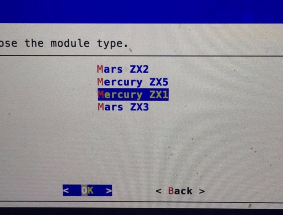
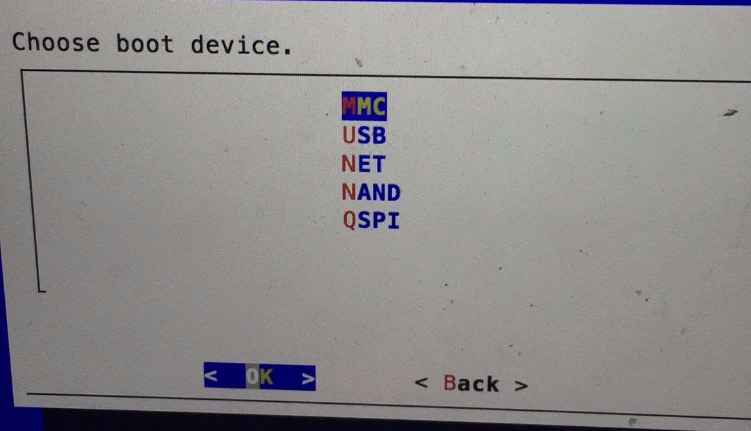
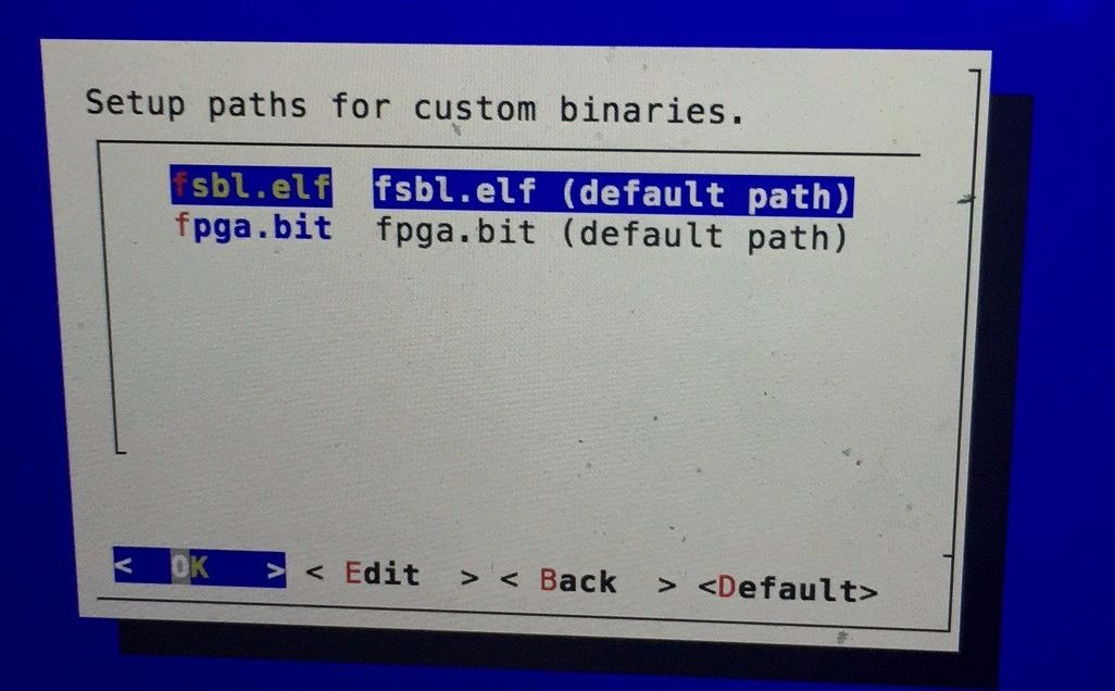
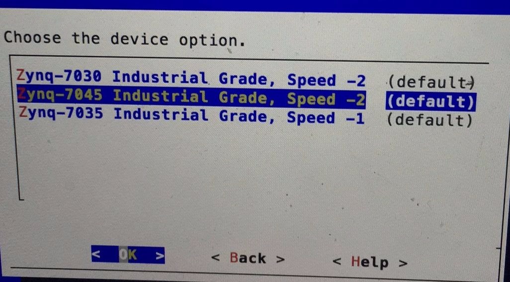
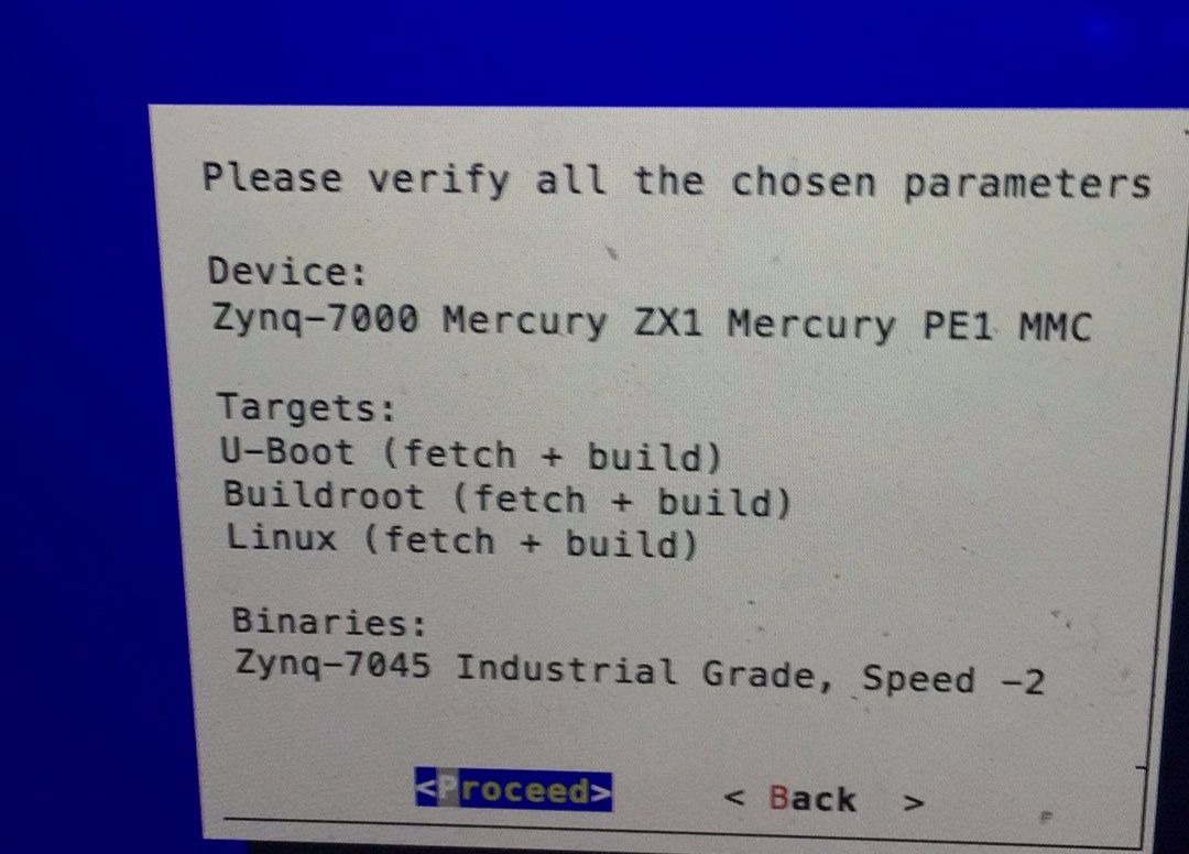
硬件启动过程

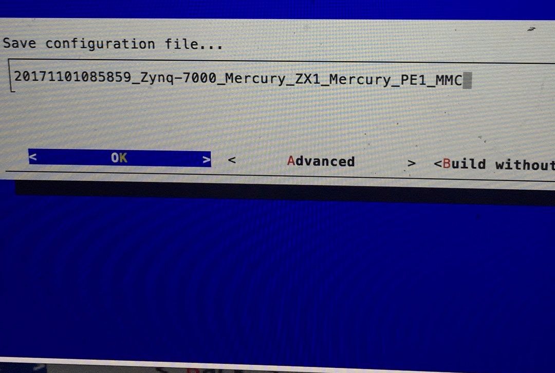
下面将会以图片的格式来说明如何利用脚本文件生成相应的文件

step1

step2

step3

step4

step5

step6

step7

step8

step9

软件启动过程

Xilinx ZYNQ7045 通过 MMC 启动过程

  • boot.scr 文件
    • u-boot在启动的时候会在第一个分区(FAT/extX格式)寻找/boot.scr或者/boot/boot.scr文件,boot.scr中可以包含用于载入 devicetree.dtb,kernel,initrd(可选)以及设置内核启动参数的uboot命令。所以boot.scr相当于是一个启动脚本文件,处理器会根据该文件设置相关的环境,加载相关的文件到指定的内存位置。
  • boot.scr 文件的生成

    bootscript = mkimage -A arm -O linux -T script -C none -a 0 -e 0 -n "Uboot mmc start script" -d bscripts/mmcboot-rootfs bscripts/uboot.scr
     # 相关参数的含义可以见网站(http://forum.lemaker.org/cn/forum.php?mod=viewthread&tid=62&page=)
     # 其中mmc-boots作为相输入文件,根据该输入文件生成输出文件
    
  • mmboot-rootfs

     run mmc_args && mmc rescan && load mmc 0 ${kernel_loadaddr} ${kernel_image} && load mmc 0 ${devicetree_loadaddr} ${devicetree_image} && run setupqspi && bootm ${kernel_loadaddr} - ${devicetree_loadaddr}
    # 该输入文件指定了加载文件以及加载地址
    

Hello World

发表于 2018-03-06 |

Welcome to Hexo! This is your very first post. Check documentation for more info. If you get any problems when using Hexo, you can find the answer in troubleshooting or you can ask me on GitHub.

Quick Start

Create a new post

1
$ hexo new "My New Post"

More info: Writing

Run server

1
$ hexo server

More info: Server

Generate static files

1
$ hexo generate

More info: Generating

Deploy to remote sites

1
$ hexo deploy

More info: Deployment

Xingguo

10 日志
2 分类
15 标签
GitHub
© 2020 Xingguo
由 Hexo 强力驱动
|
主题 — NexT.Pisces v5.1.4
本站总访问量次